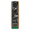

Pimoroni Pico LiPo 2 XL W - PIM776
An elongated Pirate-brand RP2350-powered board with 16MB of flash, 8MB of PSRAM, USB-C, Qw/ST, 2.4GHz wireless / Bluetooth and built-in LiPo charging.
Psst - looking to use the mighty RP2350 microcontroller as the brains in your project, but want more features than are present on a vanilla Raspberry Pi Pico 2? Pimoroni Pico boards are souped-up dev boards, with all the tasty extras baked in?
Pimoroni Pico LiPo 2 XL W is powered and programmable via USB-C and comes with an upgraded 8MB RAM, 16MB of flash storage and easy-to-read pin labels. It's got onboard LiPo/LiIon battery management - the inbuilt charging circuitry makes charging your battery as easy as plugging your board in via USB. There are two indicator LEDs connected to keep you informed of the on/off and charging status. There's also a handy power button and a BOOT button, which can also be used as a user switch.
It's super easy to connect up to things without soldering, with a Qw/ST connector (for adding I2C sensors and breakouts), a SP/CE connector (for hooking up SPI/serial breakouts) and a debug connector (for if you prefer to program using a SWD debugger).
Pico LiPo 2 XL Wow
This XL W version is equipped with a Raspberry Pi Radio Module 2, which gives it 2.4 GHz wireless and Bluetooth connectivity. To make this work without compromising, the Pimoroni crew has taken the liberty of making this board a tad longer than a standard Pico (OK, 24mm!) and used the RP2350B chip (the B stands for Big). In return, you get access to a mighty 40 exposed GPIO (spread over two 30-pin rows of headers).
If you'd prefer a similar board without the extended footprint, check out Pimoroni Pico LiPo 2!
Features
- Powered by Raspberry Pi RP2350B (Dual Arm Cortex M33 running at up to 150MHz with 520KB of SRAM)
- 16 MB QSPI flash (XiP) + 8 MB PSRAM
- Raspberry Pi Radio Module 2 provides 2.4GHz wireless and Bluetooth connectivity
- MCP73831 charger with 215mA charging current (datasheet) with XB6096I2S battery protector (datasheet)
- USB-C connector for power, programming, and data transfer
- Qw/ST (Qwiic/STEMMA QT) I²C connector + SP/CE SPI/serial connector
- 3-pin debug connector (JST-SH)
- Switch for basic input (doubles up as DFU select on boot)
- Power button + Switch for basic input (doubles up as DFU select on boot)
- Power, charging, and user LED indicators
- On-board 3V3 regulator (max regulator current output 600mA)
- Input voltage range 3V - 5.5V
- 2-pole JST PH battery connector, with polarity marked on the board
- Two rows of 30 pins, exposing 40 GPIO
- Sort of compatible with Raspberry Pi Pico add-ons. Be sure to attach them towards the USB end of the board!
Batteries, cables, and headers are not included.
Resources
- Pinout printable PDF version
- Schematic
- Pico LiPo MicroPython firmware and examples
- MicroPython examples for add-ons and breakouts
Connecting Breakouts
Pico Lipo 2 XL W has both a Qw/ST (AKA Qwiic/STEMMA QT) connector and a SP/CE connector. You can easily connect up Qw/ST breakouts using a 4-pin JST-SH to 4-pin JST-SH cable and SP/CE breakouts using an 8-pin JST-SH to 8-pin JST-SH cable.
Notes
- ⚠️ You should only use Pimoroni Pico LiPo 2 XL W with LiPo or LiIon batteries, and you should make sure that any project involving LiPos is sufficiently protected from being dented, bent, punctured, or crushed.
- Measurements: approx 77mm x 21mm x 10mm (L x W x H, including connectors)
- The user LED is wired to WL_GPIO0 of the Radio Module 2 (RM2).
- As well as being useful for putting your Pico LiPo 2 into bootloader mode, you can also use the BOOT button as a user button. It's wired to GP30 and active low. This pin is also exposed on the right-hand header, where it can be activated by connecting a switch between it and ground.
- Two of the ADC-capable pins are wired to internal functions of the board: GP43 senses battery voltage, GP47 controls PSRAM access. If your project does not use these functions but needs these pins, then cut the traces on the underside of the board labelled "BtS Cut" and "PSRAM Cut".
- VBus Sense is wired to WL_GPIO2 of the Radio Module 2 (RM2).
- For uses requiring very low power draw, the power LED can be disconnected by cutting the trace on the rear of the board labelled with a LED symbol, near the USB-C end.
- For high power draw uses over 800mA, the battery protector can be bypassed by soldering the trace labelled "+1A Mode". Make sure your battery can safely deliver this amount of current before doing this.


